

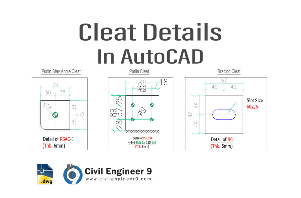
Here are the AutoCAD details of Bracing, Purlin & Stay Angle Cleat for free download to use in steel structure design.
Cleat Details In AutoCAD
Cleat Details In AutoCAD
The cleat is a structural element that people use to connect or fasten two steel components together. Builders commonly use cleats in constructing steel buildings, bridges, and other structures to securely connect different steel members.
The basic concept of a cleat in steel structures involves creating a strong and stable joint between beams, columns, or other structural members. Cleats can take on various forms, but typically, they consist of a piece of steel that someone bolts or welds to one steel member, and this piece features holes or other elements to facilitate the connection with another steel member. There are several common types of cleats that are frequently used:
- End Plate Cleat: People weld an end plate cleat, which is a flat plate with holes, to the end of a steel beam or column. This is done to connect the end of one member to another, for example, when joining two beams or attaching a beam to a column.
- Angle Cleat: An angle cleat, which is an L-shaped piece of steel with holes, is typically bolted to the flange of a beam or column. This is used to connect two members at an angle, providing additional support and stability.
- Tee Cleat: A tee cleat, which is shaped like a “T,” is often used to connect a beam to a column, offering support and transferring loads. People typically bolt or weld it to the flange of the column.
- Gusset Plate Cleat: To connect two or more members at a joint, a gusset plate cleat is used. This cleat is a flat plate with holes, and it’s bolted or welded to the members to ensure a secure connection.